As their names imply, layer 2 switch and layer 3 switch have two separate working methods.
Layer 3 switches forward packets based on their IP addresses; their next hop destination is then determined. They use routing algorithms as their routing strategy.
Layer 2 switch
If the layer 2 switches do not follow the routing algorithm, how will they learn the MAC address of the next hop?
This is achieved by following the ARP (Address Resolution Protocol).
01 ARP works as follows:
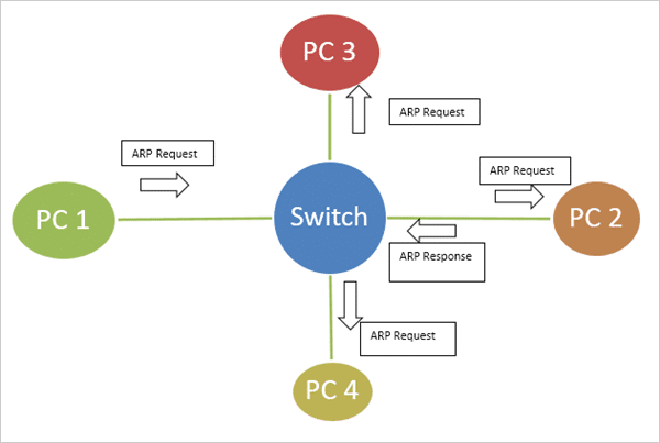
Using the network as an example, one switch is connected to four host devices, designated as PC1, PC2, PC3, and PC4. Currently, PC1 is about to send a data packet to PC2 for the first time.
Although PC1 knows the IP address of PC2 during the first communication, it does not know the MAC address of the receiving host.
Therefore, the switch sends an ARP request to all ports (excluding the port connected to PC1), and PC2 will reply with an ARP response message with its MAC address after receiving the ARP request.
In this way, PC2 also collects the MAC address of PC1.
Through the back and forth flow of the above messages, the switch knows which MAC addresses are assigned to which ports.
Similarly, when PC2 sends its MAC address in the ARP response message, the switch will collect PC2’s MAC address and store it in its own MAC address table.
From now on, whenever PC1 wants to send any data to PC2, the switch only needs to look up in its address table and forward it to the target port of PC2.
In this way, the switch will continue to maintain the hardware address of each connected host.
02 Conflict and broadcast domain
In layer 2 switching, conflicts may occur when two or more hosts attempt to communicate on the same network link at the same time interval.
When data frames collide, devices must resend the data. Collisions have a serious negative impact on network performance, so it is absolutely necessary to avoid collisions.
Broadcasting is a way of transmitting information, where a device in a network simultaneously sends data to all other devices in the network. The range of the data that can be broadcast is called the broadcast domain.
In simple terms, a broadcast domain refers to the collection of all devices in a network that can receive the same broadcast message.
Using an Ethernet network composed of one or more switches, all sites are in the same broadcast domain. As the number of switches increases, the scope of this broadcast domain also increases, which can lead to problems such as difficulty in maintenance, broadcast storms, and security issues.
As mentioned above, a host needs to send an ARP broadcast request to obtain the MAC address of another host on a different network segment.
This broadcast request will be broadcast to every host, which can easily lead to broadcast storms.
03 VLAN
In order to overcome conflicts and broadcast domain issues, VLAN (Virtual Local Area Network) technology is introduced into computer network systems.
1.There are two methods for separating broadcast domains:
Physical separation: Divide the network into several small networks physically.
Logical separation: logically divide the network into several small virtual networks, known as VLANs.
Physical separation has many disadvantages, which can make the design of local area networks less flexible, while VLANs have flexibility and scalability.
VLAN configuration is completed at the switch level by using different interfaces. Different switches can have different or the same VLAN configurations, and can be set according to the needs of the network.
Devices and users within the same VLAN are not constrained by physical location, and can be organized based on factors such as function, department, and application, allowing for communication as if they were in the same network segment.
Therefore, hosts connected to different switches can share the same broadcast domain.
To better understand VLAN, let’s take an example. One uses VLAN, while the other does not.
Without VLAN, broadcast messages sent from host 1 will reach all devices in the network.

VLAN is not used
If you add an interface card named fast Ethernet 0 and fast Ethernet 1 (usually represented as Fa0/0) to two switches in the network to configure VLAN, broadcast messages from host 1 will only be sent to host 2.
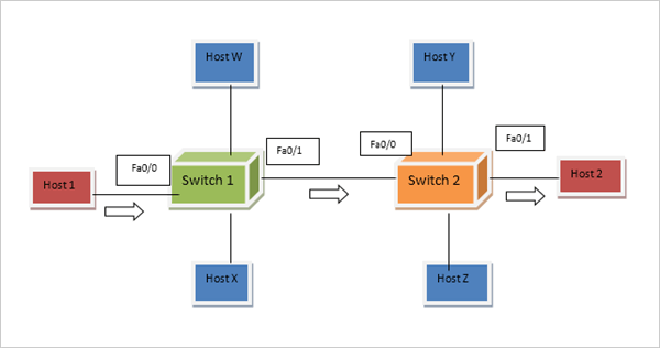
A network using VLAN
This happens during configuration: only host 1 and host 2 are defined under the same VLAN group, while other device components are members of other VLAN networks.
It should be noted that layer 2 switches can only allow host devices to communicate with hosts in the same VLAN. To reach host devices on another network, a layer 3 switch or router is required.
VLAN networks are highly secure because of their configuration type, where any file can be sent through two pre-defined, physically unconnected hosts on the same VLAN.
Broadcast traffic is also managed by it, as messages will only be sent and received to defined VLAN sets, rather than to every device on the network.
2.Access and relay ports
Various types of configurations can be completed on the switch port, and assigning an access port to a VLAN allows access to a single VLAN network.
When we only need to simply configure the host terminal device to a specific VLAN network, we will use the access port.
If you need to access multiple switches and different VLANs, configure the interface as a relay port on the switch. The relay port is intelligent enough to handle traffic from multiple VLANs.
3.Configure VLAN
To configure VLAN on the switch, first enable the IOS mode on the switch.
The command to create a VLAN is onfig mode VLAN NUMBER i.e. Switch(config)# VLAN 10.
By using interface commands, we can allocate fast Ethernet ports under VLAN.
By using the switchport access command line, we can specify the interface as the access mode.
The next command will assign VLAN numbers to switch port access modes.
Switch(config) #vlan 10
Switch(config-vlan) #exit
Switch(config) #int fa0/1
Switch(config-if) #switchport mode access
Switch(config-if) #switchport access vlan 10
The switchport access mode command can only be assigned to a single VLAN. When multiple VLANs need to be configured, use the switchport trunk mode interface command, as it can carry traffic for multiple VLANs.
Characteristics of Layer 2 Switch
The following is a list of various features of layer 2 switches.
A layer 2 switch can act as a bridge, connecting various terminal devices of a computer network system on a single platform. They can transmit data from the source end of the LAN network to the destination end very quickly and efficiently.
The layer 2 switch learns the MAC address of the destination node from the address table of the switch, performs switching functions, and rearranges the data frames from the source end to the destination end.
The MAC address table provides a unique address for layer 2 devices, identifying the terminal devices and nodes for data delivery.
The layer 2 switch divides the huge and complex LAN network into small VLAN networks.
By configuring multiple VLANs in a large LAN network, switching becomes faster without physical connections.
The following is a list of various applications of layer 2 switches.
Through layer 2 switches, we can easily send data frames located within the same VLAN from the source to the destination without requiring physical connections or being located in the same location.
Therefore, the servers of software companies can be centrally located in one place, while clients scattered in other locations can easily access data without delay, thus saving server costs and time.
Organizations can use these types of switches to configure hosts in the same VLAN without any Internet connection, thus enabling internal communication.
Layer 3 Switch
When we need to transmit data between different LANs or VLANs, layer 2 switches cannot meet the requirements.
At this time, a layer 3 switch is needed because the technology they use to route data packets to their destination is IP addresses and subnet division.
A layer 3 switch operates at layer 3 of the OSI reference model and uses IP addresses to perform packet routing.
They have faster switching speed than layer 2 switches and even faster than traditional routers because they do not use additional hops to perform packet routing, resulting in better performance.
To understand the function of a layer 3 switch, one must first understand the concept of routing.
The source device in the third layer first checks its routing table, which contains all the information about the source IP address, destination IP address, and subnet mask.
Then, based on the information it collects from the routing table, it sends the data packet to the destination and can further transfer data between different LAN, MAN, and WAN networks.
It follows the shortest and safest path to transfer data between terminal devices. This is the overall concept of routing.
Various networks can be connected together through STM links, which have high bandwidth, as well as DS3 links. The type of connection depends on various parameters of the network.
01 Characteristics of Layer 3 Switch
Implement static routing to transmit data between different VLANs. Layer 2 devices can only transmit data between the same VLAN network.
Dynamic routing is performed in the same way as routers, and this dynamic routing technology allows switches to perform optimal packet routing.
Based on the real-time network scenario, a set of multiple paths are provided to deliver data packets. The switch can choose the most feasible path to route the data packets. Currently popular routing technologies include RIP and OSPF.
The ability to identify the relevant IP address information of the switch regarding the flow direction.
It can deploy QoS classification based on subnet division or VLAN traffic tagging, rather than manually configuring switch ports like layer 2 switches.
More power is needed to operate and provide higher bandwidth links between switches, which are almost over 10Gbits.
Provide a highly secure path for data exchange.
02 Application of Layer 3 Switch
The application of layer 3 switches is as follows:
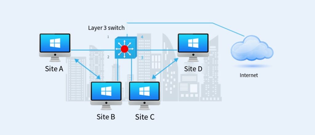
It is widely used in large-scale campuses such as data centers. Three-layer switches have the characteristics of static routing and dynamic routing, and have faster switching speeds than routers, so they are used in local area network connections for the interconnection of multiple VLAN and LAN networks.
The combination of a layer 3 switch and multiple layer 2 switches can support more users to access the network without the need for additional deployment of layer 3 switches and more bandwidth. If the number of end users on a network platform increases, it can easily be accommodated in the same operational scenario without any network enhancements.
The layer 3 switch can easily handle high bandwidth resources and end-user applications, providing 10Gbits of bandwidth.
The layer 3 switch has the ability to relieve the burden of overloaded routers. In the WAN scenario, each layer 3 switch has a primary router, so that the switch can manage all local VLAN routes.
By following the above types of scenarios, the router will work more efficiently and can be used specifically for long-distance (WAN) connections and data transmission.
The layer 3 switch is very intelligent and can use its high bandwidth to process and manage the routing and traffic control of locally connected servers and terminal devices.
Therefore, companies usually use three-layer switches to connect their monitoring servers and host nodes in the subsystem NOC center.
3.Inter-VLAN routing of layer 3 switches
The following figure shows the cross-VLAN routing operation of a three-layer switch combined with a two-layer switch.
Let’s take another example to help understand:
In universities, the PCs of faculty members and students are connected to different VLANs through layer 2 and layer 3 switches.
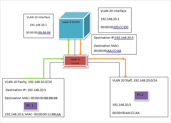
PC1, which belongs to a faculty VLAN, communicates with PC2, which belongs to another faculty VLAN.
Since the two terminal devices belong to different VLANs, we need a layer 3 switch to route data from PC1 to PC2.
Firstly, the layer 2 switch uses the MAC address table of the hardware part to locate the target host.
Then, learn the destination address of the receiving host from the MAC table.
After that, the layer 3 switch will perform switching and routing based on the IP address and subnet mask, and it will be clear which VLAN network target PC PC1 wishes to communicate with.
Once it has collected all the necessary information, it will establish links between them and route the data from the sender to the receiver. This completes the communication between different VLANs.
Differences Between Layer 2 Switches and Layer 3 Switches
01 Difference in Work Levels:
Whilst layer 2 switches operate at the data link layer, layer 3 switches focus more heavily on network layer performance to provide fast packet forwarding with optimal network performance based on varied network conditions.
02 Different Principles:
A layer 2 switch operates under the following principle: when receiving a packet from one port, when reading its source and destination MAC addresses from within it and searching its address table to identify an available port.
If there is a port corresponding to the destination MAC address in the table, data packets will be directly copied onto this port.
Layer 3 switches function by simultaneously routing and switching traffic, in other words from source to destination for one journey before passing this data back onto layer 2, so that on subsequent connections – either from source to destination or vice versa – it can be quickly switched.
03 Functions:
A layer 2 switch operates using only MAC address access and cannot be configured with IP addresses; while its counterpart, the layer 3 switch, incorporates both technologies for forwarding data at different layers.
Layer 3 switches add routing capabilities to layer 2 switches, enabling IP addresses for different VLANs to be configured as well as communication between them via layer 3 routing.
04 Application Diferences:
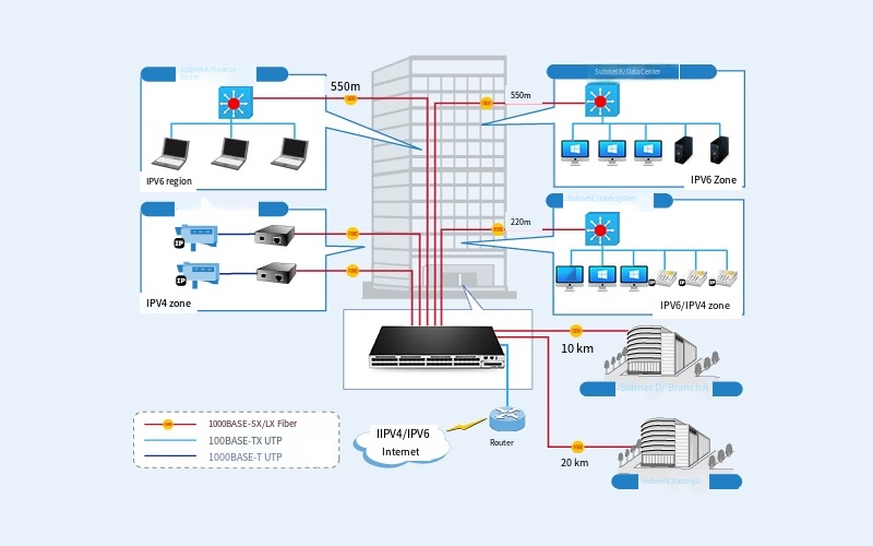
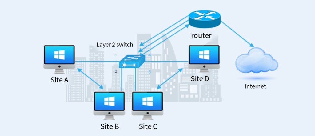
Layer 2 switches are typically employed at network access layer and aggregation layers, while layer 3 switches tend to be utilized more for network core layer functionality; although a few layer 3 switches have also been seen being deployed within an aggregation layer environment – see figure below as an illustration of their practical application in an aggregation environment. The picture illustrates this.
05 Protocol Supported:
S/n 31905-005 The layer 2 switch supports physical layer and data link layer protocols while S/n 31904-025 supports physical, data link layer, and network layer protocols.