Switch Mode
The current switch is mainly divided into box type and frame type.
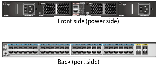
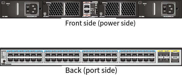
Example of Box Switch
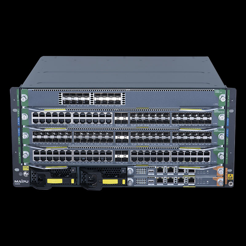
Example of frame switch
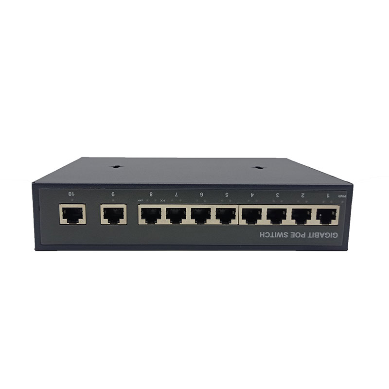
Box switch
The box switch can be understood as an iron box. Generally, the box switch is a fixed configuration, the number of fixed ports, the fixed power supply module, the fan, etc; Therefore, the box switch is not scalable.
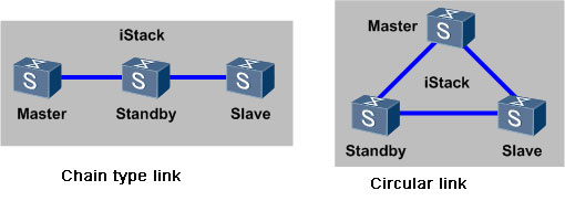
In order to improve the scalability, the box switch can support the stacking technology, and multiple box switches can be logically formed into one switch.
Under normal circumstances, the box switch shall be applied to the access layer or convergence layer of a network.
The frame switch is based on the machine frame. The interface board card, switch board card, power module, etc. can be independently configured according to the requirements. The expansion of the frame switch is generally based on the number of slots.
The frame switch is generally used at the core of a network.
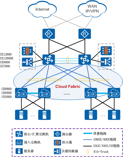
As shown in the networking above: CE5800, CE6800 and CE8800 in the data center network are all box equipment, generally used as the access layer; CE128 is a frame-type device, which is generally used as the core layer.
Therefore, box switch or frame switch can be selected according to the application level of actual switch during equipment selection.
Switch functions
Classified by work agreement layer
The switch can be divided into two-layer switch and three-layer switch.
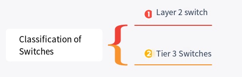
Difference between two-layer switch and three-layer switch
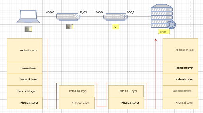
(1) Layer 2 switch
The switch works on the second layer data link layer of OSI reference model, and its main functions include physical addressing, error check, frame sequence and flow control.
As shown in the figure below, the two-layer switch works on the data link layer and can process data frames)
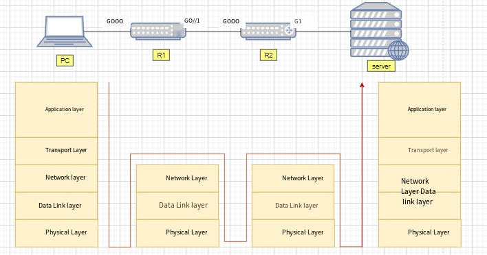
(2) Three-layer switch
A device with three-layer switching function, i.e. the two-layer switch with the three-layer routing function, but it is an organic combination of the two, and it is not a simple superposition of the hardware and software of the router device on the LAN switch.
As shown in the figure below, the three-layer switch works on the network layer and can process data packets)
Number of switch ports
Number of Box Switch Ports
The number of ports that a switch can provide is basically fixed for each type of box switch. Generally, 24 or 48 access ports and 2-4 upper connection ports are provided.
Take Oneteckcorp CE5650-48T4S2Q-EI for example (as shown below). There are 48 1000M access ports, 4 10G uplink ports and 2 40G uplink ports in total;
Number of frame switch ports
The frame switch is related to the number of configured single boards. Generally, it refers to the maximum number of ports that each frame can support when configuring the interface board with the highest density.
Taking Onetechcorp OTC12804 as an example, it supports 4 business board LPUs. The port is related to the specific single board model. Taking the 36-port 100G single board as an example, there are 144 100G ports plugged in the single board.
How to select a switch according to the number of ports
The selection of switch shall be based on the current business situation and future scalability. The number of switch ports represents the number of terminals you need to access.
Taking a switch with 48 access ports as an example, if one terminal occupies one port, then one switch can connect 48 terminals. If it is a company with 200 people, 5 such switches are required.
Switch port rate
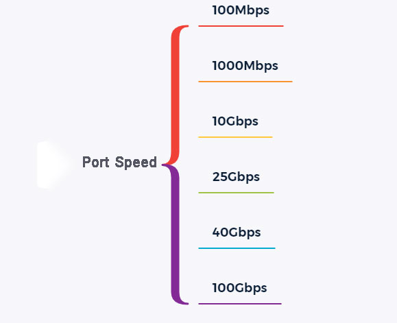
Switch support port rate
At present, the port rate provided by the switch is 100Mbps/1000Mbps/10Gbps/25Gbps, etc.
Switch port rate unit
The unit of switch port rate is bps (bit per second), i.e. how many bits per second.

Switch capacity
Also known as backplane bandwidth or switching bandwidth.
The switching capacity is the maximum data throughput between the switch interface processor (or interface card) and the data bus.
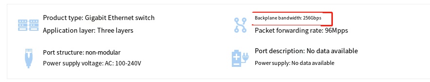
Backboard bandwidth indicates the total data exchange capacity of the switch, in Gbit/s.
The higher the switching capacity of a switch, the stronger the data processing capacity, but the higher the design cost.
The sum of all port capacities shall be less than two times the switching capacity to achieve full duplex non-blocking switching.
The switching capacity is related to the system of the switch
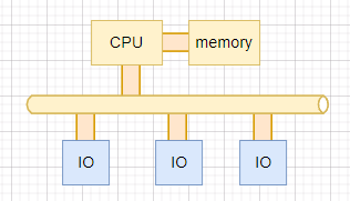
(1) For bus switch, the switching capacity refers to the bandwidth of backplane bus;
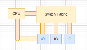
(2) For switching matrix switch, the switching capacity refers to the total interface bandwidth of switching matrix.
This switching capacity is a theoretical calculation value, but it represents the maximum possible switching capacity of the switch.
The current switch design ensures that this parameter will not become the bottleneck of the whole switch.
Switch packet forwarding rate
Packet forwarding rate, also known as interface throughput, refers to the data packet forwarding capacity on an interface of the communication equipment, usually in pps (packet per second).
Packet forwarding rate of switch is generally measured result, which represents actual forwarding performance of switch.

Packet forwarding rate calculation method
Packet forwarding rate is measured based on the number of 64 byte data packets (minimum packet) sent per unit time.
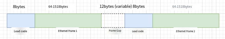
Fixed overhead of preamble and frame gap shall be considered when calculating packet forwarding rate.
By default, the frame gap is a maximum of 12 bytes, and the default configuration is recommended.
If the user modifies the frame gap of the interface to a small value, the receiving terminal may not have enough time to receive the next frame after receiving a data frame, resulting in packet loss due to failure to process the forwarded message in time.
We know that the length of an Ethernet frame is variable, but the processing capacity used by the switch to process each Ethernet frame is independent of the length of the Ethernet frame.
Therefore, when the interface bandwidth of the switch is certain, the shorter the Ethernet frame length is, the more frames the switch needs to process and the more processing capacity it needs to consume.
Selection of video surveillance switch
In high-definition network video monitoring system, there are often customer feedback screen delay, jamming and other phenomena, which are caused by many reasons, but in most cases, the configuration of the switch is not reasonable, resulting in insufficient bandwidth.
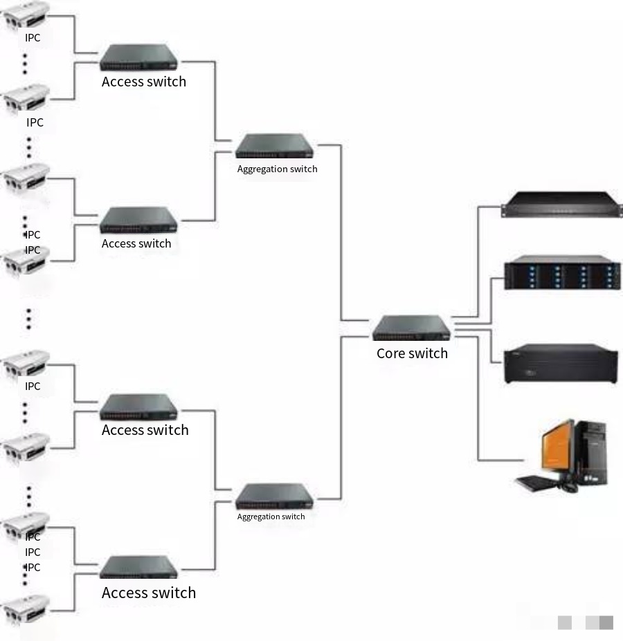
From the perspective of network topology structure, a medium-large high-definition network video monitoring system shall adopt three-layer network architecture: access layer, convergence layer and core layer.
Selection of access layer switch
The access layer switch is mainly used for downlink front-end HD camera and uplink convergence switch.
How many 720P IP cameras can be accessed by a 100M access switch based on the code stream of 720P IP camera 4M?
The actual bandwidth of the commonly used switch is 50% – 70% of the theoretical value, so the actual bandwidth of a 100M port is 50M-70M.
M * 12=48M, so it is suggested that a 100M access switch can access 12 720P IP cameras at most.
At the same time, considering that the current network monitoring adopts dynamic coding mode, the peak value of camera code stream may exceed 4M bandwidth, and considering the bandwidth redundancy design, it is best to control one 100M access switch within 8 sets, and it is suggested to adopt gigabit port if more than 8 sets.

Selection of convergence layer switch
The convergence layer switch is mainly the downlink access layer switch and the uplink monitoring center core switch.
Generally, convergence switch shall be two-layer switch with gigabit upload port.
Still, based on the code stream of 720P IP camera 4M, there are 6 720P IP cameras on each front-end access layer switch, and the convergence switch is connected with 5 access layer switches.
The total bandwidth under the convergence layer switch is 4M * 6 * 5=120M, so the cascade interface between the convergence switch and the core switch shall be gigabit interface.
Selection of core layer switch
The core layer switch is the core of the whole HD network monitoring system, mainly including the downlink convergence layer switch, the video monitoring platform of the upper monitoring center, the storage server, the digital matrix and other equipment.
When selecting the core switch, the bandwidth capacity of the whole system and how to configure the core switch improperly must be considered, which will inevitably lead to the failure of smooth display of video images.
Therefore, the monitoring center shall select the full gigabit port core switch.
If there are many points, VLAN shall be divided, and three-layer full-gigabit port core switch shall be selected.
Attachment: Parameters determining switch performance
Backplane bandwidth:
Backboard bandwidth calculation method: port number * port speed * 2=backplane bandwidth. Taking Huawei S2700-26TP-SI for example, this switch has 24 gigabit ports and two gigabit upper ports.
Backplane bandwidth=24 * 100 * 2/1000+2 * 1000 * 2/1000=8.8Gbps.
Packet forwarding rate:
Calculation method of packet forwarding rate: number of fully-configured GE ports × 1.488Mpps+number of fully-configured 100M ports × 0.1488Mpps=packet forwarding rate (theoretical throughput of a gigabit port is 1.488Mpps when the packet length is 64 bytes and 0.1488Mpps when the packet length is 64 bytes).
Take Huawei S2700-26TP-SI as an example. The switch has 24 gigabit ports and two gigabit uplink ports.
Packet forwarding rate=24 * 0.1488Mpps+2 * 1.488Mpps=6.5472Mpps.
How about this? How much do you know about the selection of switch?
Of course, what type of switch is selected, except for the number and bandwidth of these ports mentioned above
In a real project, as a sales or pre-sales engineer, you must first consider the price of the switch and the financial strength of the customer.